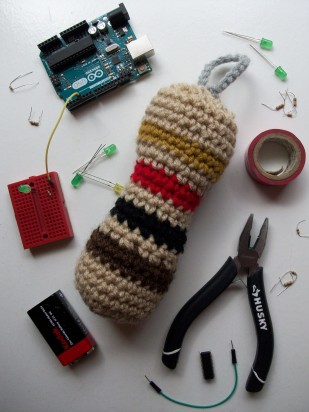
Exciting news: I got featured on the Make: blog for a project I’ve been working on for a while: amigurumi resistors rendered in crochet. Basically it’s a really soft and cute form of the resistor.
I recently picked up the new SparkFun LED Array – 8×7 to try out some hardcore charlieplexing, and so far it’s been working great.
Quoting Wikipedia, charlieplexing is
“…a technique for driving a multiplexed display in which relatively few I/O pins on a microcontroller are used to drive an array of LEDs. The method uses the tri-state logic capabilities of microcontrollers in order to gain efficiency over traditional multiplexing.”
Charlieplexing itself is a simple idea and can be an extremely efficient way of making an LED grid. However, laying out the wiring of a charlieplexed grid, whether on a breadboard or a PCB, can be complicated and require a bit of thinking. It’s easy to layout a grid with 12 or 20 LEDs, but once you start trying to make grids with 30 or more LEDs, it gets a little crazy.
I love SparkFun’s 8×7 LED Array because it eliminates the need to go through the long process of designing and wiring together the grid. Plus it’s in a neat compact module that can be easily embedded. Out of the box, all I had to do was solder on headers and plug it directly into the digital pins on my Arduino. I didn’t need to wire any external resistors, as they’re already built into the board.
SparkFun has made an Arduinolibrary for controlling the array that allows you to easily write text and draw shapes and do other interesting things on the grid. However, I wanted to use my array with my Raspberry Pi’s GPIO for the purpose of making an archaic internet-connected game system. I’ve written a single-file class in Python 3 for controlling the array with the Raspberry Pi’s GPIO, called pythonic-charlie, and you can find it here (my first legit GitHub repo! Woot woot!). It’s still under development, and still has bugs that need smoothing, but it allows you to display a list of coordinates, test the grid to verify that it’s wired properly, and display a neat little screensaver. I’m currently working on something that will display text.
If you ever wanted to learn how to charlieplex LEDs, SparkFun’s 8×7 LED Array is a really great place to start.
Recently I found that I was at a loss for my digital multimeter (confession: it’s actually my dad’s, which I’ve been borrowing for an indefinite period), and I needed to test the continuity on a PCB. So I quickly scrapped together some parts to make a simple light-up continuity meter.
Continuity meters are used to test whether two components or joints in a circuit are continuous, or directly connected. Most multimeters have a continuity meter built-in. When you touch the meter’s test probes to 2 different, yet connected spots on a breadboard or PCB, the meter will either beep or light up.
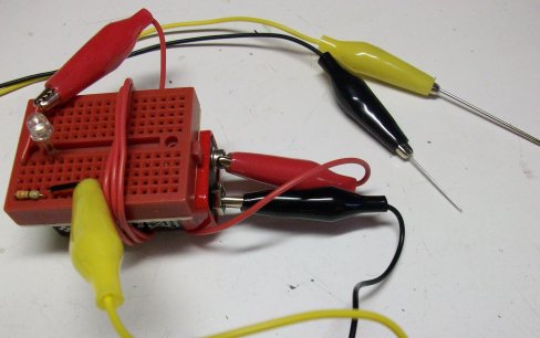
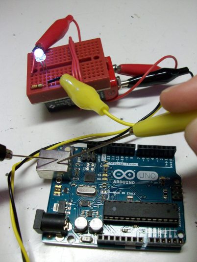
My continuity meter lights up when the test probes are connected. I utilized a small breadboard, three alligator clips, a super bright white LED, two needles, electrical tape, and a 330Ω resistor to make my meter. I didn’t have to use any solder, and after I used the excess wire to wrap the breadboard and the battery together, it came together nicely. It works well!
Here’s how to make your own!
Materials Needed
You’ll need the following, depending on how you want to make your continuity meter and what parts you have.
alligator clips and breadboard (or soldering iron)
x2 needles (act as test probes, if you want something more precise than the wire as a test probe)
x1 battery or combination of batteries with a combined voltage of 1.5 to 9V, the total voltage being greater than but as close as possible to the voltage drop of the LED
x1 resistor, ohm value discussed later
x1 LED, you’ll want to know its voltage drop (see here if you don’t know, you’ll have to scroll down a bit)
electrical tape, duct tape, or glue for keeping the meter together after assembly
Assembly
The hardest part of building your continuity meter is figuring out the right resistor value to use with the LED. For that, will use a bit of math and Ohm’s Law. You’ll need to know the voltage of your batteries (Vcc) and the voltage drop of your LED (Vd). The forward current limit (I) on most LEDs can be approximated to 0.02A or 20mA, so we’ll use that as our current value. This is how to calculate the resistance (R) of the resistor you’ll need:
V = IR
R = V/I
R = (Vcc – Vd) / I
R = (Vcc – Vd) / 0.02
For my continuity meter, I had an old 9V battery that measured at 8V and a white LED with a forward voltage drop of about 3V. So I needed an ((8V – 3V) / 0.02mA) = 250 Ω resistor. The closest standard value resistor up is 330Ω, which is what I used.
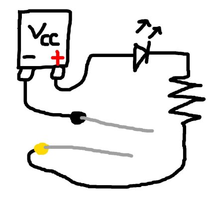
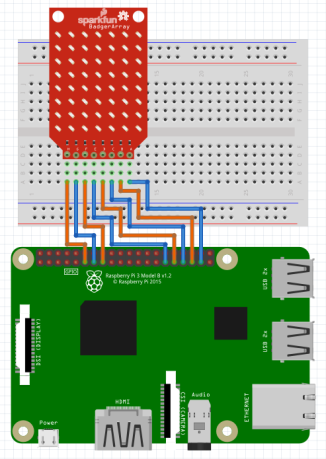
Next comes assembly. Whether you’re using a soldering iron or a breadboard, it’s simple. Either solder your ‘test probes’ to the wire, or put the needles directly into the alligator clips. Take a look at the diagram below for guidance.
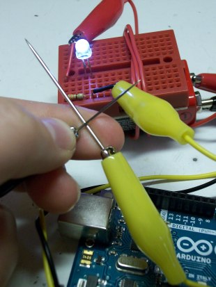
That’s about it. The LED should light up when you touch the two test probes! To containerize your continuity meter, duct tape the battery and excess wires to the breadbread, or if you soldered it, you can try gluing it together.
Important Disclaimer about using this continuity meter:
Be careful using your continuity meter. I’d recommend using it only for testing boards and components where you know that things are supposed to be continuously connected. You don’t want to use it as you’re trying to figure out what a board does, you run the risk of shorting out components on the board. Definitely don’t use your homemade continuity meter on circuits that have live power!
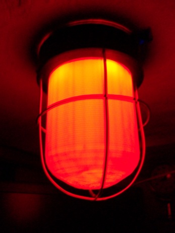
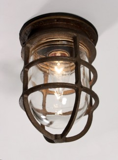
While panning absentmindedly through one of my dad’s farm/tools/random-outdoorsy catalogs, I saw something that really caught my eye: a cagelight that apparently was intended for use in a barn, but looked like it belonged in a mad scientist’s lab. It looked something like this:
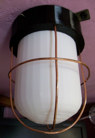
I immediately decided I needed to make my own version of the cagelight for use as an epic decoration for my mad-sciencey desk. I used some thick wire, LEDs and other electronics, 3D printed parts, and lots of hot glue. It turned out to look like this:
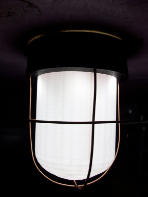
This project consisted of two main parts: making a custom PCB to control the light, and designing an authentic cagelight enclosure. I ended up designing and 3D printing a custom case and using heavy gauge wire to make the cage. Below is what it looks like lit up. It’s quite bright. Basically, a battery powers some white LEDs and some flashing red LEDs which can be switched on and off.
Take some time today to do a little project with your Arduino!
Testing a Power Relay
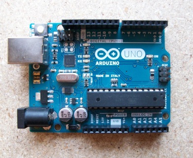
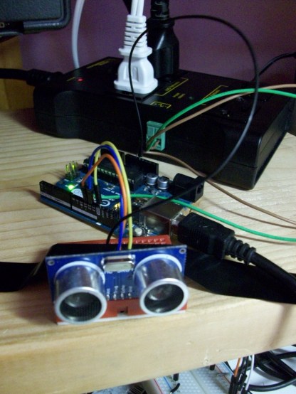
My tech savvy grandma recently got me a very nice IoT power relay! I spent a while testing it out by making a simple system to automatically turn my desk light and my Pi monitor on or off. I hooked an SR-04 ultrasonic sensor to my Arduino Uno and wrote a sketch to have it detect when my hulking mass is close to my desk and send a signal to turn the relay on or off.
This is my power relay setup connected to an Arduino and ultrasonic sensor. I taped the ultrasonic sensor down to keep it from wiggling about. The Arduino is being powered by a USB port on my Pi 2.
The most challenging part of creating this little system was getting accurate readings from the ultrasonic sensor. They can read inaccurately if objects are moving around in front of the sensor, and the light would flicker annoyingly if I moved too quickly. I figured out how to smooth the value by reading from the sensor 30 times in 1.5 seconds, and then taking the average of all 30 values.
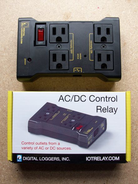
The power relay works great. It required no setup out of box, and it’s simple to connect your controller. Its only disadvantage is that it doesn’t have an ‘always-on’ power source, which requires you to have an external power source for the device controlling the relay.
This is the power relay I tested.
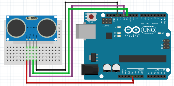
Check out the sketch I wrote for this project below, or click here to download.
/*
Using an Arduino with a Power RelayParts used:--ultrasonic sensor--desk lamp
--Arduino Uno--120v relayThis sketch uses an ultrasonic sensor to detect whethera person in near or sitting at a desk, and sends a signal to a power relay to turn desk lighting on or off.*/#include<NewPing.h>constintLIGHT=10;constintTRIGGER=12;constintECHO=11;NewPingsonar(TRIGGER,ECHO);voidsetup(){pinMode(LIGHT,OUTPUT);}/* The main loop iterates every 2.5 seconds. */voidloop(){/*In order to get a accurate measure of whether someone is near, we read the ultrasonic sensor 30 times and take the average. That way, if the ultrasonic sensor reads sporadically as it occasionally does, those values will be averaged out. This takes 0.05 * 30 = 1.5 seconds to get a value from the sensor. */while(inti,i<30,i++){sum=sum+sonar.ping_cm();delay(50);}intaverage_distance=sum/30;/* Using the value, we send a signal to the relay depending on whether someone is detected less than 130 cm away. We also pause for a second for good measure. */if(average_distance<130){digitalWrite(LIGHT,HIGH);delay(1000);}else{digitalWrite(LIGHT,LOW);delay(1000);}}
It’s been a good long while since I’ve really dissected a bit of electronics. But I finally got another chance after uncovering an old broken CD/radio/cassette player in the basement! After some tests, I determined that the CD player part of it didn’t work. Since no one uses archaic cassette tapes anymore, and a radio that weighs ten pounds is pretty impractical, I naturally snapped it up to tear it apart. 🙂
The boombox before dissection; note that it’s quite dusty. It was manufactured in 1997 so it was about 20 years old.
Disassembling it was pretty trivial. There was only a few screws which held the casing together, and each internal part also held in place with screws. The most challenging part was removing the large speakers. Each was both glued and screwed, so it took a little extra prying to get them off.
The boombox can be powered from both batteries and the house current, so there’s both a transformer and a large compartment to hold eight D cells. There’s one large PCB that combines the circuits for the CD player, cassette player, and radio player, with a few offshoot PCBs to connect the controls.
I was able to salvage some good parts:
x1 2-digit 7 segment display
x2 DC motors (they’re rather weak)
x2 8Ω 3W speakers
x1 microswitch
x1 large potentiometer
x1 fancy radio-tuning gear
a few plastic casings for switches and knobs
various wires and connectors
Check out the following images of the torn-apart boombox.
In the event of the Raspberry Pi’s 4th (1st) birthday, I’ve been working on a tic tac toe arcade game using the Raspberry Pi’s GPIO with Python. Basically, a human player battles against the computer on a 3×3 LED grid. The player uses a pushbutton 4-way keypad with a ‘select’ button to play. I also added a speaker and coded some neat sound FX!
Below is a demo of the game:
Hardware
Parts used for the tic tac toe game
The hardware for this project is pretty basic:
Raspberry Pi
9x green LEDs
5x pushbuttons
Speaker
Trim potentiometer
9x 330Ω resistor
5x 10kΩ resistor
Adafruit Pi Cobbler with ribbon cable
Wiring schematic for tic tac toe made with Fritzing
LED Grid Diffuser
In order to make the playing experience more pleasant, I designed a 3×3 grid LED light diffuser and 3D printed it so as to make the light from the LEDs less blinding. It also keeps the LEDs lined up nice and covers some of the wires up too!
Computer AI
This was actually my first experience dealing with any computer AI, and I discovered that it is quite fun! I designed it so it has four logical steps:
First, if there’s any move where the computer will win (i.e. the computer already has two in a row), the computer will play that move.
Second, if the player could win on the next turn, the computer will block it.
Third, if the center of the board hasn’t been played, the computer will play the center.
Finally, if none of the options above are applicable, the computer will play a random move not already played.
Software
For the software, click here. It’s written in Python 3 with the RPi.GPIO library, and it’s actually the longest bit of code that I’ve written as of yet. 🙂
Here’s an extra video with more info about the project:
Building the final prototype for the tic tac toe gameCloseup of LED grid and buttons
I’ve made my first video tutorial! I obtained some SR-04 ultrasonic sensors quite cheaply, and I’ve been learning how to use them with the Arduino, with good results. I’ve created a tutorial covering how to get the proper libraries and how to use the basic functions in the Arduino IDE to interface with the sensor.
Here’s the steps (covered in the video) on how to get NewPing, a library created for controlling ultrasonic sensors, up and running with the Arduino IDE:
My latest mini-project has been hooking an analog joystick up to an Arduino to make my own joystick computer mouse…plus I have some news…
I got a soldering iron for Christmas! YAY! I desoldered an analog joystick from an old PlayStation 2 controller (see my Tear Down from a while back), and bought a joystick breakout board from SparkFun so I could fit the joystick into a breadboard. I originally made my own breakout board using a PCB etching kit, but it just got messy and I decided to save myself the hassle and just buy one.
This is the breakout board I was making for the joystick. It didn’t come out too good, as I drilled the holes too big and the solder ran through.
I practiced using my soldering iron quite a bit over the holidays and I feel like I’m finally getting the hang of it! I soldered the joystick along with some old headers from a furnace board without a hitch!
This is the finished analog joystick soldered to the breakout board.
I then wired it up on the breadboard, along with my Arduino Micro (which can emulate a mouse and keyboard, unlike most of the other Arduino boards), an LED indicator light, a toggle switch, and two pushbuttons to act as right and left click mouse buttons. The toggle switch shuts the mouse on and off, and the LED indicates if it’s on or off. I tested it out on my laptop and my Raspberry Pi, and it works great! Certainly it’s more interesting to use a joystick than a regular mouse!
Okay, okay, so this is kind of an off-topic post. But it does involve engineering design and materials engineering, so I thought I’d share it.
A couple of months ago, I entered a national competition to design an eco-friendly helicopter of the future. I didn’t win, but I wanted to share what I came up with! I had a lot of fun coming up with ideas, and I learned quite a bit about the physics and jargon of helicopters.
I designed my helicopter to be ultralight, entirely self-powered, and sensor-integrated to increase safety and efficiency. I named it the 459 AeroFish because it’s all-terrain and can easily float on water. The 459 part is completely arbitrary though, it was a random number that I thought sounded good.
The best part of my helicopter is that it’s made of aerogel, a super lightweight gel that’s made of 98% air and is one of the world’s best thermal insulators.
Image of Aerogel from Wikipedia
The 459 AeroFish is powered in two different ways. During startup and sustained lengths of travel, the helicopter uses hydrogen fuel, which is zero emissions and can be derived from the environment. Current methods of mining liquid hydrogen are extremely expensive both monetarily and energy-wise, but in the future hydrogen could be easier to obtain as the collection methods improve.
The 459 AeroFish’s prime power source, though, comes from millions of microscopic nanogenerators embedded in the aerogel skin of the helicopter. These nanogenerators are capable of converting the vibrative energy of wind turbulence into an electric charge that can power the helicopter’s engine. By reducing the aerodynamic drag on the helicopter, the overall energy required to power the helicopter decreases!
The helicopter has an inflatable pontoon, which can be used to land in water. It also has landing struts that can fold in like an airplane’s to further reduce drag during flight.
The following is a detail drawing I did of my helicopter, including a close-up of the nanogenerators. This and the elevation image above were created using Adobe Photoshop Elements based off of my original hand drawing.
Below is the abstract I wrote about the helicopter if you want to read about the details.
The 459 AeroFish is an extremely lightweight aircraft that is able to sustain its own energy source through the use of piezoelectric nanogenerators and hydrogen fuel cells. Intended for human search and rescue, wildlife conservation, and scientific research, especially in aqueous environments, the 459 AeroFish can land competently on both land and water. It has an extremely large non-stop flying range (approx. 1100 km) and it can dock safely in bodies of water for long periods of time with the help of its inflatable pontoons. Scientists can use the helicopter to conduct oceanic and biological research far out on the open sea, as well as in isolated biomes such as wetlands, islands, marshes, and the arctic. The long range also helps first-responders and military units in major disaster areas carry out sustained search and rescue operations.
The 459 AeroFish is constructed out of organic aerogel (an extremely low density substance made of over 99% air), carbon nanotubes, and six composite rotor blades. The 459 AeroFish’s small form factor, lightweight construction, and turbulence reduction due to the nanogenerators make it as aerodynamic as possible. The AeroFish is also equipped with sophisticated sensor integration and an internet-connected computer information system. Sensors located in the front of the body, in the aerogel exterior, and within the moving parts provide information such as the amount of energy being gathered by the nanogenerators, the stress on the rotor blades, and the condition of the engine parts and electrical system. This data, which is projected in 3D on the helicopter’s windshield, helps the pilot (or autopilot) steer the aircraft more efficiently, budget energy, and determine if parts are in need of repair or replacement before they become a problem.
The 459 AeroFish is entirely self-powered. Piezoelectric nanogenerators provide the main source of energy during the flight dynamic. Millions of tiny nanogenerators are embedded into the surface of the aerogel skin of the helicopter, and they convert the mechanical energy of wind turbulence into electrical potential. Because of its conductive properties, the aerogel is able to store the generated electricity. The nanogenerators not only generate electricity, they also reduce the force of wind turbulence on the helicopter, converting kinetic energy into electric potential.
In order to start up and sustain its power over long periods of flight, the 459 AeroFish also is powered by liquid hydrogen fuel. This fuel is stored within the carbon nanotubule hexagonal exoskeleton, so it does not take up space within the helicopter’s engine or main motor system. Alkaline fuel cells located in the rear of the helicopter’s body generate electricity by converting hydrogen and oxygen into pure water. The water can then be dispelled out of the helicopter, used as drinking water by passengers, or be electrolyzed to form more liquid hydrogen fuel.
Besides its sustainable energy system, the 459 AeroFish’s entire outside surface is made from an inexpensive biodegradable substance called safe emulsion agar gel (SEAgel), a type of organic aerogel. This ultra-light material, with a density less than that of air, consists of air-dried agar, a natural material derived from sea algae. SEAgel is even edible, and is easily replaced should the helicopter be surface damaged. The SEAgel aerogel on the AeroFish contains the nanogenerators and stores their electricity. In addition, due to its heat insulative properties, also keeps the temperature inside the helicopter comfortable for the passengers.
The 459 AeroFish is radically different compared to today’s helicopters. It is designed to be extremely lightweight and therefore require less energy overall. Instead of being made from aluminum alloys and steel, the copter consists mainly of aerogel and carbon nanotubes, making it up to six times lighter than contemporary helicopters of a similar size. The extractable landing struts as well as its overall aerodynamic smooth shape reduce in-flight drag even more.
The biggest advantage of the 459 AeroFish over the conventional helicopters of today is its combination of a few small improvements that make a vast difference in performance. The helicopter’s energy efficiency and energy sustainability make it emissions safe and zero cost to power. The inflatable pontoon and landing strut combination turn it into a versatile land or water aircraft. It’s computer information system and sensor integration make piloting easier, safer, and more efficient.

 I recently picked up the new
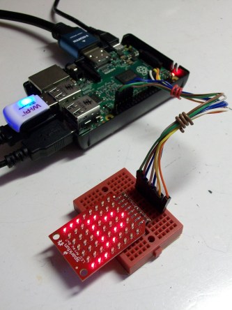
 Recently I found that I was at a loss for my digital multimeter (confession: it’s actually my dad’s, which I’ve been borrowing for an indefinite period), and I needed to test the continuity on a PCB. So I quickly scrapped together some parts to make a simple light-up continuity meter.
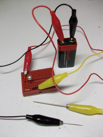 Continuity meters are used to test whether two components or joints in a circuit are continuous, or directly connected. Most multimeters have a continuity meter built-in. When you touch the meter’s test probes to 2 different, yet connected spots on a breadboard or PCB, the meter will either beep or light up.