

Here’s the perfect amateur maker project: a self-built giant seven-segment display that will awe all those who watch it in action! You only need a Raspberry Pi and a handful of regular LEDs and resistors, plus a breadboard. You can 3D print a case or you can use a paper template printout of the display. This project is versatile, I’ve provided Python 3 code for the Raspberry Pi, but you could use anything like an Arduino Mega or Beaglebone, you’ll just have to write your own software. Why, you ask, couldn’t I just use a standard 3 cm $0.99 seven-segment display? Because you can’t DIY and it’s not half as cool!
BoM (Bill of Materials):
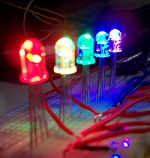
- 21 red 5mm LEDs
- 21 330 ohm resistors
- Raspberry Pi B+ or Pi 2 with peripherals
- Adafruit Raspberry Pi Cobbler Plus w/ ribbon cable (not required by HIGHLY recommended)
- Full-Size breadboard
- 3D printed seven-segment display case with seven segments OR if you don’t have a 3D printer, this paper printout here (I recommend cardstock or similar for opacity and durability) with a standard paper holepunch
- Assorted wires and jumper wires
- Small piezo buzzer (completely optional, just if you want countdown sound effects)


Steps:
- The first step is to properly position the LEDs and their power and ground connections. Start by putting the Adafruit T-Cobbler to the far right side of the breadboard, all the in the last set of holes.
- Next, we’ll wire each segment one by one. Refer to the diagram below, just starting with the LEDs and their resistors to ground; in the next step we’ll add the jumpers to the pins. The center three segments require a bit of maneuvering to get the resistors and jumpers into place. Make sure not to clip the resistor leads too short, and it may be helpful to use some needle-nosed pliers to get the resistors in place without ripping up other LEDs.
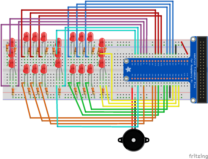
- Finishing up the LEDs and their resistors to ground, now we can wire each LED to a pin on the Raspberry Pi. You can either copy the wiring shown here, or you can make up your own wiring. If you do your own pin wiring, make sure you keep careful track of which pin is part of which segment, either on paper in some working code variables.
- Optional step: If you want to add a small piezo buzzer for countdown sound effects, now’s the time. Connect it to pin 21 and span it directly to the ground rail. Or, if you did your own pin-numbering connect it to any free pin.
- Now for a bit of wire management: make sure all your jumper wires are underneath the LEDs so that they don’t get in the way of the segments and casing.
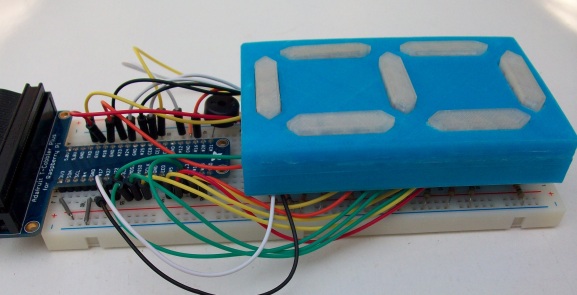
- If you have a 3D printer: Print the casing and seven segments from here. Test fit each hole in each segment with an LED to make sure an LED fits. Put a segment over each set of three LEDs, and fit the casing over all the segments. You’ll have to bend the LED leads a bit so it fits, and the first time you put the casing on will be a bit of challenge.
- If you don’t have a 3D printer: Print this seven-segment cutout here. Cut it out on the dotted lines and then holepunch each symbol. Now fit the cutout over the LEDs. Note that it’ll be a bit tough to fit it over the LEDs the first time; you’ll likely have to bend the LED leads quite a bit to get it to work.
- The hardware is all finished! At this point the display should be making you giddy with happiness, but it’ll be even better once it’s got some software! Warm up your Raspberry Pi and open up your favorite text editor to write some Python code!
- Check out the code here. It’s got lots of comments that explain how the code works. Make sure if you wired your pins differently, you change the variables to reflect your wiring. When you get the code running you’ll be able to display numbers, do a 9-0 countdown, and do some cool animations!
- Troubleshooting: if some of your LEDs aren’t working double check they could be burned out. Replace them and if they still don’t work check your connections to the pins. Finally, check your variable assignments; one error can make the whole display act strangely.
- Now you’ve got a working XL seven-segment display, with five GPIO pins to spare! Now you can stare at the mesmerizing numbers all day…


The Origins of This Project Plus Future Developments
I was inspired to make this after seeing some 3D printable large seven-segment displays on Thingiverse. Because my Printrbot Play 3D printer has such a small build dimension, I designed my own, slightly smaller display and got to work with my Raspberry Pi. I made the display small enough that you can simply use a breadboard, which makes it different from other large seven-segment displays.
There is plenty of room in the back of the 3D printed case so that you can make a custom PCB if you like (I won’t attempt that now; I still have to develop my terrible soldering skills!), and there’s screw holes so you can also mount it to something. I’m currently working on a charlieplexing solution to reduce the pins used for the display from 21 down to 6. That way I’ll be able to use an Arduino Uno, add another display (another display would add a whole lot of potential), or add more components.

